There has been some discussion on the ATMList mailing list that I have been monitoring about diagonal assemblies. For those that don't know, a Newtonian telescope, the kind I am making, has two mirrors, the big one at the bottom of the tube, and the small one at the top of the tube near the eyepiece. That small one is known as a secondary mirror or the diagonal mirror (or both) and it diverts the reflection of the star from the center of the big tube to the edge where the eyepiece can get to it. There are as may ways of making sure that the diagonal stays in one spot (or not) as there are telescope makers. But people on the ATMList share a lot of ideas. On sacrosanct rule is to make the support for it tiny so that it doesn't block too much light as it enters the scope, but make it stiff enough to do the job. To that end, an idea of using thin wires, guitar strings, and arranging them like guy wires on an old fashioned airplane. Its simple, can be made really stiff, and it's light weight, and I won't have to cut any sheet metal and keep it flat at the same time. The hard part will be making the attachment points for the ends of the wires. I don't want it to look like something I cooked up in my shed. I'll think of something though.
The other discussion I was interested in was how to hold the big mirror. There are elaborate designs out there with little closely spaced triangles of metal each supporting a small area of the back of the mirror so it doesn't flex however minuscule. But they are hard to make, and according to engineering analysis tools I've used, they don't do much more for me that a 6 point design. My mirror is 12.5 inches across, and 2.1 thick, so its not going to flex very much anyway. But even if it were 1.5 inches thick it would still make sense to use the 6 point design.
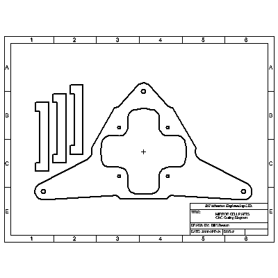
Here is an image of the design I plan on making. It's made of 1/2 inch 6061 aluminum that is easily found on EBay for under $20. The drawing shows the cutting diagram that the machine shop will need to cut it with their water jet cutter.
 He said he would charge me $25 to do that part. Most of that would be setup time, and that once he started cutting, it could be way more complicated than the lines I have drawn here. There are three little bars, and the main piece. The central opening is big enough to attach a little muffin fan for cooling the mirror should I desire. The bars attach diagonally on the two sides and at the bottom.
  The mirror lays on top of the bars, and is held there with RTV. One thing to note is that the adjustment screws located at the corners of the triangle are not evenly located around the central opening. That is because they form a right triangle which I think will be more intuitive to use when adjusting the telescope's alignment. Here is another image of the assembly so that you can see how the bars attach with one screw each. The bars pivot, however minutely around those screws. The ends of the bars will actually have 3/4 inch round metal pad attached to them made from welding nuts. That will give a bigger surface for the RTV. I'll post more pictures when I actually finish this sucker.

No comments:
Post a Comment